Stop Hammering Your System!
Mitigate Risk on Your Water Supply System Through Hydraulic and Surge Modeling
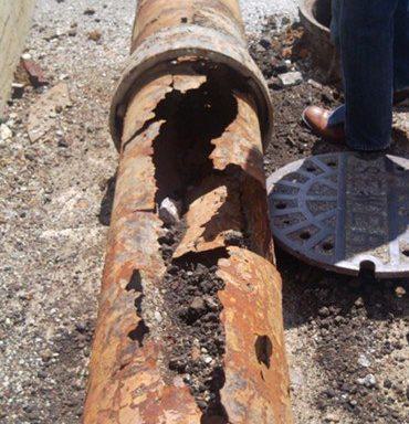
Uncontrolled pump shutdown can lead to the undesirable occurrence of water-column separation, which can result in catastrophic pipeline failures due to severe pressure rises following the collapse of the vapor cavities.
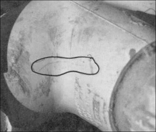
A water supply system is subjected to "water hammer" whenever there is a change in steady-state condition such as pump stoppage, pump startup, or valve closure. As a system changes from one steady-state condition to another, there is a transient change in flows and pressures as the system settles to the final steady-state condition. These pressure swings can have a negative impact on aging infrastructure in the system causing unnecessary main breaks, property loss, and water quality concerns.
High transient pressures can cause damage or main breaks if the transient pressure exceeds the pressure rating of the pipe and pipe joint restraint system. Low pressure waves resulting from a pump trip or power failure can have several undesirable impacts. Low pressures have the potential to allow contaminants to enter a pipeline causing potential health risk. Examples of chemical contaminants include fertilizers, pharmaceuticals, solvents and microbial contaminants are an even greater concern because even with dilution, some microbes could cause an infection with a single organism. If the pressure falls below the vapor pressure of water, serious damage can occur as the result of the formation and collapse of pockets of water vapor. This phenomenon is known as cavitation.
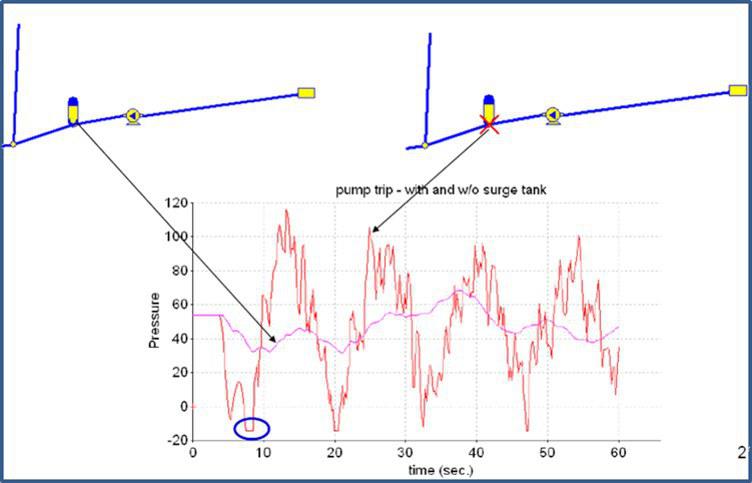
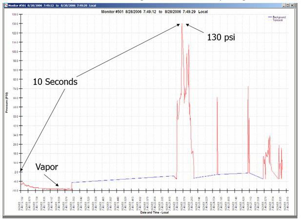
Hydraulic and surge modeling can be used to identify what assets could be at risk and aid utilities with cost-effectively making critical upgrades to improve the reliability of their systems. A surge model is a representation of a piping system that calculates both hydraulics and transient waves and accounts for friction, wave speed, and flow/pressure changes over time in short term increments (e.g.. Milliseconds). Surge models are sensitive to parameters that are not easily predicted, so conservative assumptions can lead to exaggerated transient results. This can lead to incorrect or excessive engineering recommendations. The model must be properly calibrated - this will verify/refine assumptions, allow for system specific representation, and enable a better understanding of system issues. Benefits of a properly calibrated model include confidence in model results, optimization of operating strategies, optimized selection and sizing of surge control devices, and the minimization of overall life cycle costs. Surge models can be calibrated in several ways, ranging from hydraulic calculation to SCADA to pressure data to field pressure data, which is the best method of calibration.
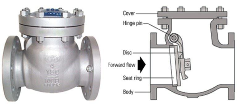
Surge mitigation devices delay the change of flow or discharge of water from line so that rapid or extreme fluctuations in the flow are minimized. Check valves prevent flow from reversing through the pump. Timing and rate of closure should be set to protect the pump and discharge system. Surge relief angle valves are designed to prevent damage from water hammer in the system by opening when the system pressure exceeds the set shut-off pressure of the valve disc. As the disc opens, the surge pressure rise that caused it to open is spilled and dissipated through the open valve. When system pressure drops below the set shut-off pressure, the valve disc slowly closes against the oil contained in the cushion chamber and cylinder. Surge relief valves are designed with a smooth flow and minimal obstruction to flow for efficient surge relief. Air and vacuum valves allow excess air to escape and allow air to enter a pipeline during valve closure or system shutdown. Allowing the air to enter the pipeline during low pressure situations helps to prevent a possible main collapse and water hammer cause by sudden flow reversal.
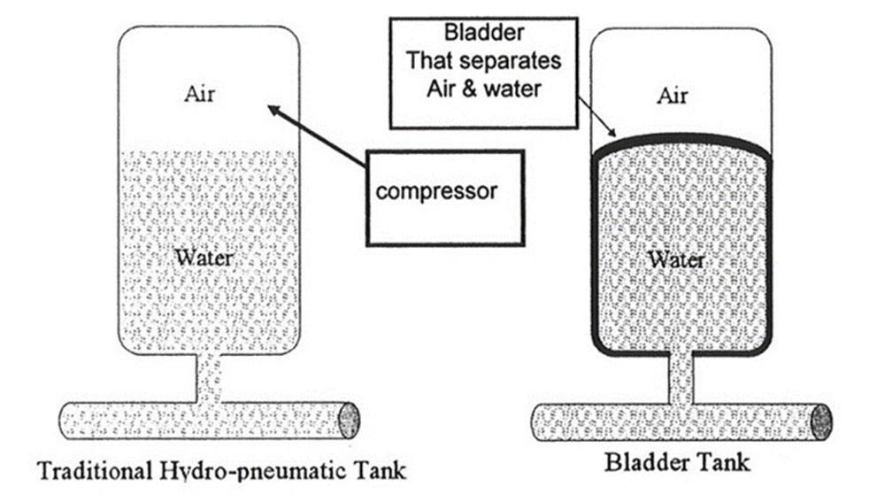
Hydropneumatic tanks, or pressurized surge vessels, are especially useful to mitigate transients caused by rapid pump start-ups and shut-downs. They are filled with water at the bottom and entrapped gas over the liquid. They help to mitigate both positive and negative pressure problems in the system. Hydropneumatic tanks are usually located near the discharge side of a pump station. Compressor vessels consist of a vessel containing water and a pre-calculated volume of compressed air in order to give the required elasticity to push the water at the required rate into the system. Because the water is in constant contact with the air, air dissolves into the water and the control system is activated to replenish the air, which eventually reappears elsewhere in the system. In a bladder system, the liquid is contained within a butyl rubber bladder (compatible with drinking water). A pre-charge pressure is calculated to give the required elasticity to push the water into the system. Once the vessel is commissioned into service and the correct pre-charge is introduced, the vessel will continue to operate automatically emptying when necessary and refilling with the return waves until reaching its steady state balance.


